return link

Wednesday, 30 January 2019

Some Zeiss/Contax lenses under expose by half a stop!

This is a continuation of a previous post on how the Contax lenses communicate to the camera body in which I mentioned I was doing some investigation into some questions I had and also some forum posts that suggested some lenses had compatibility issues with some Contax bodies.

To deal with the second issue first - I've not been able to duplicate any of the problems I've seen mentioned that might suggest some incompatibility between some lenses and bodies. I suspect these problems were due to individual lenses or bodies that had one or more faults.

I have, however, determined that the information passed from the lens to the body differs between lenses and that means, in some cases, certain lenses will cause a half stop under exposure.

The questions I had were raised by references in a few different Contax body service manuals to a feature called 'theta compensation'. This is something that appeared to relate only to some lenses. I initially tried to discover what theta compensation was but have been unable to find anything. Even an email to Zeiss was unproductive with Zeiss saying all the information was passed to Yashica. So I took a different approach and started to look at individual lenses that appeared to have theta compensation to see if I could find a difference between them and other lenses.

I was able to identify two lenses in my collection that have theta compensation. I was able to do this because those lenses have a different tab that couples to the AE/MM switch on the body. The AE/MM switch on the body is usually referred to as the 'theta switch' in the service manuals and it has three positions. The first, normal, position indicates an AE lens is fitted, the third position indicates an MM lens is fitted, but there is a second, middle, position that indicates an MM lens with theta compensation is fitted. So lenses that have theta compensation have a narrow tab that only moves the switch to the middle position.

Here's a couple of pictures of two of my lenses that show the difference. I've outlined the tag on the lens in red and the switch lever in green so their shapes and positions are more clear. The first is a 85mm f/2.8 MM lens. Note the tag is pushing the switch all the way to the end of its travel.


The second is a 50mm f/1.7 MM lens. Note the tag on the lens is notched and it only pushes the switch half way.


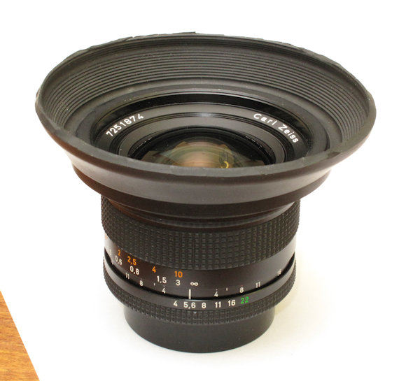
Besides the 50mm f/1.7 MM, I also found the 18mm f/4 MM had the same shaped tag so that is the second lens I have that has the feature.

To try and ascertain if there were any differences between lenses with and without theta compensation, I set up a test rig using the mirror box from a 139. The mirror box has the lens mount attached and the various couplings to the lens and has a potentiometer (variable resistor) directly coupled to the aperture stop down ring of the lens mount. By measuring the resistance of the potentiometer with various lenses attached and at all apertures, I was able to plot graphs of resistance against the number of stops the lens was stopped down. Here's a picture of the rig and the results.


The X axis is the number of stops the lens is stopped down. The Y axis is the measured resistance.

What is clear from this is there are two distinct groups of results with one group shifted by half a stop from the other. Two of the lenses in the group shifted to the right are the 50mm f/1.7 MM and the 18mm f/4 MM which had previously been identified as having theta compensation. Surprisingly, the third lens in this group is a 50mm f/1.7 AE lens. This is surprising as the AE lenses were designed and manufactured before MM cameras were brought out and before there was any method of detecting that such a lens had been fitted to the body. As a check that this wasn't just a fault of the individual lens, I tested a second 50mm f/1.7 AE lens and got identical results.

The second test I did was to check the position of the maximum aperture lever for each lens. In the 139 the lever is coupled mechanically to the aperture display so there's nothing that could be measured other than physical position but it was clear that the lenses that exhibited the half stop shift in the aperture stop down lever, also had a half stop shift in the position of the maximum aperture lever.

Here's the inside view of the maximum aperture lever (arrowed). You can see the black marks on the chassis where I've recorded the position for different lenses.


My first thought was that these two half stop shifts would cancel each other out so there would be no effect on the metering but it's not that simple. In the 139, for instance, the maximum aperture lever plays no part in the metering, it is only used to display the correct aperture in the viewfinder. The metering is done purely from the potentiometer coupled to the aperture stop down ring. So, not unsurprisingly, lenses that have theta compensation under expose by half a stop when used on a 139. This is easily confirmed by metering a scene with a lens with theta compensation then again with a lens that doesn't. The half stop difference in the meter reading is quite obvious.

With other MM bodies I thought the exposure error might not happen but I tested an RX, RXII and a 167 and it does happen and in all metering modes.

Conclusions

In the 167MT service manual there are some tables that show the aperture associated with each position of the aperture stop down lever and the maximum aperture lever. The tables have two different values, with a half stop difference, for lenses with and without theta compensation. This effectively confirms my findings that the physical position of these levers differ on lenses with theta compensation. Or, put another way, any particular position represents a different value on lenses with theta compensation to ones that don't.

You would think, therefore, that the MM bodies would carry out a different exposure calculation depending on the position of the AE/MM switch. I have tried manually changing the position of the switch but it makes no difference to the meter reading. Either my expectations are inaccurate, or the bodies don't have the theta compensation feature fully implemented.

Clearly I'm not able to test every combination of lens and body in every metering mode - I don't have examples or the time - and it may be that the half stop change in metering only affects a few lenses, but the phenomenon definitely exists. Whether it's a problem is for individuals to decide. Does half a stop error in metering matter? In the days when I used to use transparency film, I would have said it does.

If anyone has anything to add to this I would be very interested to hear from them. If you have seen the issue with particular lenses then which ones and with which bodies and in what metering mode? Also, if you find any lenses that display the wrong aperture in the viewfinder when other lenses are OK, I would be interested in the same information. And, finally, if anyone has any idea what theta compensation is (specifically related to the lenses under discussion), please let me know.

(Edit)

There was one other test I did which I failed to mention above, probably because it produced no useful information at the time. However, on reflection, the fact it showed no difference between lenses with theta compensation and those without is relevant. The test was to attach the lenses to my A7, digital camera, and check for differences in meter readings. The A7 has no connections to the lens and simply measures the light passing through it. The result was there is no difference in the light transmitted between lenses with, or without, theta compensation. This is significant because, if the lenses with theta compensation did transmit a half stop more light, the apparent half stop under exposure would be correct and make all the above rather inane.

(Edit 2)

I recently discovered the 50/1.7 MM lens, when attached to an RTS body, will cause the aperture readout in the viewfinder to be half a stop out. So, for example, with the lens set to f/5.6 the aperture display will show the aperture as between f/4 and f/5.6.

Sunday, 27 January 2019

The Bitser

Bitser (Bitzer): "A thing that is made from parts that originally did not belong together."

I acquired another 139 parts camera recently. These are cameras that have too many problems to make it economical to repair. They end up in my 'parts camera' drawer and get regularly picked over when I'm in need of a part to repair another camera. I have nine or ten I guess, some of which are little more than a chassis with a few parts left attached. As I was adding the most recent one to my collection, I thought about the possibility of making a complete, working, camera out of the various bits and pieces.

Always up for a challenge, I picked out the best chassis I could find as a starting point. The chassis had a shutter, which tested as OK, along with the film advance mechanism, which had a problem, and the electronic PCB. A mirror box with a clean viewfinder came from another camera. The top plate and all the other parts came from several other donors.

With the film advance issue resolved, I assembled all the parts onto the chassis, cleaning and lubricating etc. along the way. I wanted to fit a base plate with a serial number that was of the correct period for the modification level of the camera. The chassis I used had the last version of the transfer switch and the mirror box had the later version of the release magnet and associated mechanism, so I needed a base plate with a high(ish) serial number. I found just one that fitted the bill. It was a bit bent and dented but a couple of blocks of wood and a hammer got it into shape and soon fitted.

The final thing, after a full function and film test, was to add some covers. I had some freebies supplied by Aki-Asahi and, in the spirit of using up what I had, I fitted those. I actually think they are OK though not a colour I would normally use. I also had some matching winder covers and so a winder I acquired with a camera recently got a quick overhaul and new covers fitted to complete the look.

I'm not sure I'm going to give it much use but I like how it looks and find it satisfying to have built a complete camera from spare parts. It will sit on the shelf for a while until I decide what to do with it.


Tuesday, 1 January 2019

Documents Update

I've added the 167MT service/repair manual to my documents page.

Also a couple of other lens data sheets and some Yashica service info.

Saturday, 29 December 2018

Zeiss Contax 18mm f/4 Lens Hood - part 2

I managed to get a few example images of the lens with and without the hood.

This one is indoors with the sun coming through a window and falling onto a plain wall. I folded the hood back then just angled the camera until I saw the flare, took one picture then pulled the hood forward - flare gone.


This second example was taken outside. I did the same procedure as before.


The second pair of pictures have another area of flare that wasn't removed by the hood. It's not obvious so I've ringed it in the next picture.


 I could also get the lens to produce some more obvious flare even with the hood in place so it's not a 100% solution, but hoods never are. But I think it's a worthwhile addition.

I also wanted to add a note to say that the lens I have is an MM type with a serial 72*****. There was, apparently, an earlier version of the 18mm which may behave completely differently.

Friday, 28 December 2018

Zeiss Contax 18mm f/4 Lens Hood

The 18mm f/4 doesn't have a filter thread. It takes 70mm push-fit accessories and Zeiss made a 70mm to 86mm ring to take 86mm filters and which they also suggest will act as a hood. The problem now is the difficulty in finding one and then the probably extortionate cost you'll have to pay for it. At the time of writing, there is one on ebay with a buy-it-now price of $110 with shipping from Japan so, in the UK at least, there will also be VAT and import duty etc. to pay on top - no thanks.

As I've found the 18mm is a bit prone to flare, I thought I would look for an alternative. What I found was a hood for a Mamiya 45mm lens for the 645 system. It is a 70mm push fit hood and fits perfectly straight onto the 18mm. I paid about £20 for mine including postage. This seems a typical price. The only problem is is that it's a bit deep so I took a knife to it and cut it back (rather badly as it happens).

The hood has a square section on the front. Not  a lot of use with the 18mm as the front of the lens rotates so it's impossible to keep the hood square. Some experimentation suggested the whole square section needed removing anyway to stop vignetting on the 18mm so that's what I did. You end up with a round hood so it doesn't matter that it rotates.

Here's a few pics.


Some testing afterwards showed there was a tiny amount of vignetting in the corners so I trimmed another, maybe, 3mm off it which cleaned up the cut edge and got rid of the last bit of vignetting.


Being such a wide angle lens, a hood is never going to be very effective but it's better than nothing. I'll see if I can get some example shots with and without the hood to show the difference.

Just one thing of note, there is a Mamiya hood available that is said to fit the 645 45mm lens and also the 65mm RB67 lens. This is not the correct hood. The original version of the 45mm had an 80mm diameter front and that hood is for the original version lens. Check what is written on the side of the hood. It should be as shown in my picture above. If it mentions RB67 lenses, it's the wrong one.

(Edit: There is now a second part to this post with some examples).

Thursday, 27 December 2018

The Contax/Yashica Bayonet

This might seem a particularly boring subject to write a blog post about but it's intended to be the first of a few posts regarding the information that get's passed to the camera body from the lens. This has been prompted by some questions I had and which I'm in the process of doing some investigation of. Also, the suspected incompatibility between some lenses and camera bodies suggested by some forum posts but yet to be confirmed.

Rather than try and cover everything in one long post I thought I would split it up and start here with a general explanation of the linkage between lens and camera.

Besides the bayonet itself, there are, up to, four points where the lens and body couple together. Earlier AE lenses had three then a fourth was added to MM lenses to tell the camera a MM lens is attached. The diagrams show the points of contact on the body and the lens with a description of each below.


Aperture Linkage Pin/Lever (Aperture stop down lever). The pin on the lens rotates as the lens aperture is changed and couples to a lug (described as a lever in the diagram) on a ring that rotates around the camera lens mount and which, in turn, couples to a device that converts the position of the ring into an electrical signal. On earlier cameras this was done using a potentiometer (variable resistor) which was part of the metering circuit. On later cameras, the potentiometer was replaced by an encoder that outputs a digital code.

The value passed to the camera represents the number of stops that the lens has been stopped down from maximum. It doesn't represent an actual aperture value.

Aperture Scale Coupling Pin/Lever (Maximum aperture lever). The 'pin' on the lens may actually be a lever or a shaped lug depending on the lens. It is in a fixed position that represents the maximum aperture of the lens. It couples with a lever on the body to transfer this information to the camera so that it can display the actual aperture in use. On earlier cameras a mechanical system, that linked the maximum aperture information and the number of stops the lens has been stopped down, was used to display the aperture in use. On later cameras with electronic displays it is done electronically.

The Contax S2/S2b and some Yashica cameras that don't have an aperture display in the viewfinder, don't use this feature.

Automatic Diaphragm Action Pin/Lever. This lever is driven from the camera and causes the lens to stop down to the selected aperture. On later MM cameras when used in shutter priority or program modes, this lever will move just the correct amount to stop the lens down to the required aperture.

AE/MM switch (not shown on diagram). On MM lenses, an extra lug was added which extends just beyond the bayonet mount and engages with the switch on the camera. The switch is a three position switch. The first, default, position is for AE lenses (AE lenses don't have the extra lug so the switch doesn't move). The third position is for MM lenses but there is also a mid position which I intend to be the subject of one of my following posts.

Sunday, 8 April 2018

DIY repairs update

Just updated my DIY repairs page with some information regarding reassembly. An area I've generally ignored in the past but I've had a few people contact me with reassembly issues and this covers those issues.